Fan Engine Safety Valve
Fan engine safety valve is a new type of valve that produced and developed by our company's research of traditional safety valve problems, combined with the the specific conditions and parameters of fan engine. It is used to protect the safety of fan engine and equipment, when the fan engine and equipment pressure abnormal rise to a specified value (safety valve opening pressure), the safety valve can automatically open and discharge media, to prevent the pressure continuing to rise, when the pressure of fan engine and equipment reduce to a specified value (The back seat pressure of safety valve), the safety valve automatically closes. The product has obtained national patent.
compared with traditional safety valve, it has the following features:
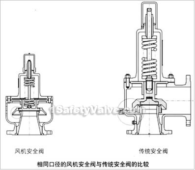
1、As the fan engine is mainly used for low-pressure air medium, so fan engine safety valve removes the outlet discharge flange, and adopts the holes, which uniformly distributed around the body, to discharge medium directly. Meanwhile setting the spring cavity directly in the back of disc, after using the aboved patented structure, the valve structure is more compact and medium discharge is more smooth, while the weight of the valve is only 1 / 3 ~ 1 / 5 of a traditional safety valve.
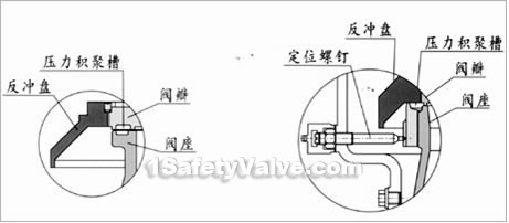
2、Fan engine safety valve adopts patent structural design of pressure build-up tank between the disc and seat, compared with the traditional safety valve using regulative ring and dog screw structure, the structure is more simple and the use is more convenient, while the performance is more stable.
3、The minimum opening pressure of traditional safety valve usually is 0.1MPa, while the safety valve used for the fan, its opening pressure is often required less than 0.1MPa, the traditional safety valve even uses the low stiff spring, it also can not be accurate and sensitive acting in the low pressure. While the design opening pressure scope of fan engine safety valve is 0.02 ~ 0.2MPa, so fan engine safety valve can act accurately and sensitively in the low pressure.
4、Fan engine safety valve spring acting point is very close to disc sealing surface through the stem force acting to the disc, whereas the traditional safety valve acting point is far from the disc sealing surface, therefore, in comparison with traditional safety valve, the acting performance of fan engine safety valve is more stable and reliable.
5、The traditional safety valve discharges medium in one direction through the outlet pipe, so the system will be vibrated when discharge the media, while the fan engine safety valve discharges medium all around uniformly through the holes that ditributed around the body, therefore, the valve acts smoothly without vibration.
6、Fan engine safety valve does not have adjustable ring, the use is very simple, the opening pressure of safety valve have been debugged according to customers requirements before delivery, the user can use directly after installing the safety valve on the system.
Type,materials and main parameters
| nominal pressure | type | |||||||
| PN1.0MPa | AF4QH-10C | AF4QW-10P | AF4QW-10P8 | AF4QW-10P3 | AF4QW-10R | AF4QW-10R8 | AF4QW-10R3 | |
| the materials of main parts | body | WCB | ZG1Cr18Ni9Ti | CF8 | CF3 | ZG1Cr18Ni12Mo2Ti | CF8M | CF3M |
| bonnet | WCB | ZG1Cr18Ni9Ti | CF8 | CF3 | ZG1Cr18Ni12Mo2Ti | CF8M | CF3M | |
| seat | 2Cr13 | 1Cr18Ni9Ti | 0Cr18Ni9 | 00Cr19Ni10 | 1Cr18Ni12Mo2Ti | 0Cr17Ni12Mo2 | 00Cr17Ni14Mo2 | |
| disc | 2Cr13 | 1Cr18Ni9Ti | 0Cr18Ni9 | 00Cr19Ni10 | 1Cr18Ni12Mo2Ti | 0Cr17Ni12Mo2 | 00Cr17Ni14Mo2 | |
| recoil plate | 2Cr13 | 1Cr18Ni9Ti | 0Cr18Ni9 | 00Cr19Ni10 | 1Cr18Ni12Mo2Ti | 0Cr17Ni12Mo2 | 00Cr17Ni14Mo2 | |
| stem | 2Cr13 | 1Cr18Ni9Ti | 0Cr18Ni9 | 00Cr19Ni10 | 1Cr18Ni12Mo2Ti | 0Cr17Ni12Mo2 | 00Cr17Ni14Mo2 | |
| spring | 50CrVA | 50CrVA(the surface packed with fluoroplastic) | ||||||
| suitable temperature | 250℃ | 180℃ | ||||||
| applicable medium | air and other low corrosive gas medium | nitric acid corrosive gas medium | acetic acid corrosive gas medium | |||||
| spring pressure class MPa | 0.02~0.035;0.035~0.045;0.045~0.06; 0.06~0.08;0.08~0.11;0.11~0.15;0.15~0.20; | |||||||
Displacement
| opening pressure MPa | discharge pressure MPa | nominal diameter | ||||||
| DN40 | DN50 | DN80 | DN100 | DN125 | DN150 | DN200 | ||
| displacement Qd,m3/min | ||||||||
| 0.02 | 0.022 | 5.5 | 9 | 22 | 37 | 62 | 88 | 137 |
| 0.03 | 0.033 | 6.8 | 11 | 27 | 45 | 76 | 108 | 169 |
| 0.04 | 0.044 | 7.6 | 12 | 30 | 51 | 85 | 120 | 188 |
| 0.05 | 0.055 | 8.6 | 14 | 34 | 58 | 96 | 136 | 213 |
| 0.06 | 0.066 | 9.4 | 15 | 37 | 63 | 105 | 150 | 234 |
| 0.07 | 0.077 | 10 | 16 | 40 | 68 | 113 | 160 | 275 |
| 0.08 | 0.088 | 11 | 18 | 43 | 73 | 121 | 172 | 269 |
| 0.09 | 0.099 | 12 | 19 | 46 | 77 | 128 | 183 | 285 |
| 0.10 | 0.11 | 12 | 20 | 48 | 81 | 135 | 192 | 300 |
| 0.11 | 0.121 | 13 | 21 | 51 | 85 | 142 | 202 | 316 |
| 0.12 | 0.132 | 13 | 22 | 53 | 89 | 148 | 211 | 331 |
| 0.13 | 0.143 | 14 | 23 | 55 | 93 | 156 | 222 | 347 |
| 0.14 | 0.154 | 15 | 24 | 58 | 94 | 161 | 231 | 361 |
| 0.15 | 0.165 | 15 | 25 | 60 | 102 | 170 | 241 | 377 |
| 0.16 | 0.176 | 16 | 26 | 63 | 106 | 176 | 250 | 391 |
| 0.17 | 0.187 | 16 | 27 | 65 | 110 | 184 | 261 | 407 |
| 0.18 | 0.198 | 17 | 28 | 68 | 114 | 190 | 270 | 422 |
| 0.19 | 0.209 | 18 | 29 | 70 | 118 | 197 | 280 | 438 |
| 0.20 | 0.22 | 18 | 30 | 72 | 122 | 204 | 290 | 453 |
Main dimensions, weight and structure
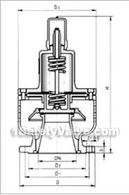
| nominal diameter DN | main dimensions(mm) | weight(kg) | ||||||
| D | D1 | D2 | b | Z-φd | D3 | H | ||
| 40 | 145 | 110 | 85 | 16 | 4-18 | 100 | 250 | 5 |
| 50 | 160 | 125 | 100 | 16 | 4-18 | 115 | 272 | 6 |
| 65 | 180 | 145 | 120 | 18 | 4-18 | 140 | 285 | 6.3 |
| 80 | 195 | 160 | 135 | 20 | 4-18 | 172 | 296 | 6.5 |
| 100 | 215 | 180 | 155 | 20 | 8-18 | 212 | 425 | 14 |
| 125 | 245 | 210 | 185 | 22 | 8-18 | 254 | 450 | 22 |
| 150 | 280 | 240 | 210 | 22 | 8-23 | 280 | 480 | 35 |
| 200 | 335 | 295 | 365 | 24 | 8-23 | 330 | 520 | 50 |
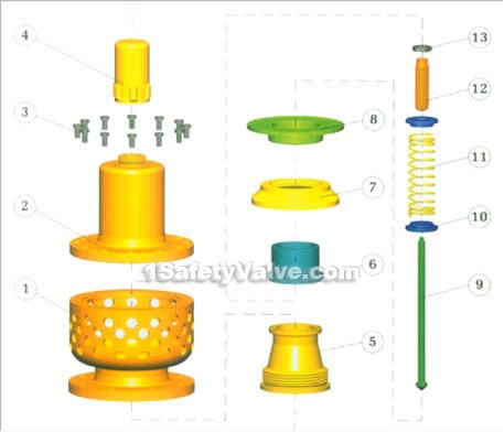
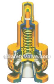
1.body, 2.bonnet, 3.screw, 4.cap, 5.seat, 6.disc, 7.recoil plate, 8.guided sleeve, 9. stem, 10.spring seat, 11.spring, 12.adjusting bolt, 13.locking nut


